.png)
IMPORTANT NOTE:
This is a summary of the full HDX User Guide, provided by
Nureva. We strongly recommend that you
read this in full prior to purchase / installation of any HDX system.
This overview is provided by Ascentae as a basic guide of
what to look for to ensure a smooth installation of HDX systems in a typical
deployment. As such, advanced
functionality such as integration with 3rd party subwoofers, Adaptive
Voice Amplification and Adaptive Voice Lift are not included in this overview. Additional guidance for these scenarios can
be found in the full HDX User Guide.
For the purposes of this overview, all rooms are considered
to be regular shape. For details of
options in irregular shaped rooms, refer to the full guide.
As this guide is provided as a pre-installation reference,
it does not cover the installation process.
Details of installation best practice can be found in the full guide or
on the Nureva support site – support.nureva.com.
The full HDX guide can be found here - https://www.nureva.com/user-guide/hdx
HDX Overview
The Nureva HDX series is a mutli-component audio system
which is suitable in spaces up to 223m2. It consists of 3 elements –
Providing full range distributed audio, adaptive voice lift, adaptive voice
amplification, full room microphone coverage, assisted listening via Auracast
and full connectivity to UC platforms (Teams, Zoom etc).
The HDX series offers 5 modular configurations, consisting
of 3 components.
System Hub
All in one system eliminating need for separate DSP’s, amps and Bluetooth transmitters
-
AV-over-IP for single cable installation
-
Bluetooth audio streaming
-
Auracast broadcast audio
-
Intelligent compute features including camera
tracking, controller integration & device management
-
Passive cooling for quiet operation
Sleep mode for energy conservation | 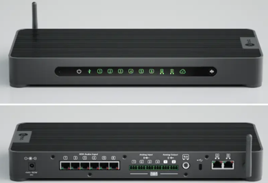 |
Audio Bars Speakers / microphones combined in single, easy to install unit to support distributed audio. -
Full range distributed audio and full room
microphone coverage
-
2-way speaker system with tweeter & dual
woofer
-
2 dimensional microphone array
-
Single Ethernet connection to hub Flexible horizontal or vertical installation - Flexible horizontal or vertical installation | 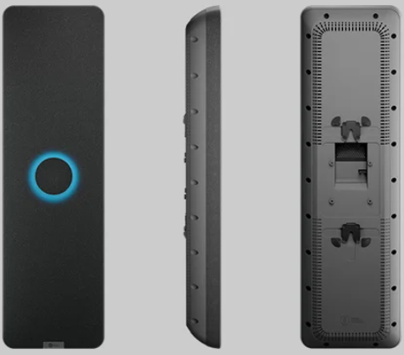 |
Microphone Pod (option)
Spports Microphone Mist for improved full room coverage
-
2 dimensional microphone array
-
Single Ethernet connection to hub
-
Flexible installation on wall or ceiling | 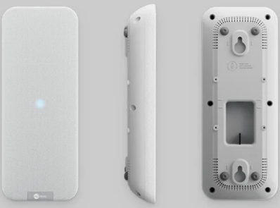 |
HDX Configurations
Prior to purchasing a HDX system consider the following
-
Room Dimensions – get accurate measurements of
room
-
Active locations – note where people speak,
seating & presenter areas and if there is a ‘front of room’
-
Room environment – consider which physical
locations are best for HDX component placement
-
Room acoustics – assess reverberation &
background noise to determine best placement for HDX components.
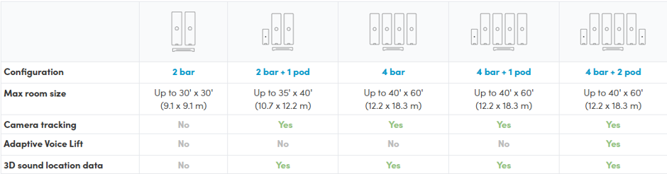
Coverage for each HDX configuration is based on the length
of the longest wall. For rooms with a
more complex geometry, consider a larger configuration or add microphone pods
to provide best coverage.
-
2 HDX Audio bars are suitable for rooms up to
91.m in length
-
4 HDX Audio bars are suitable for rooms up to
18.3m in length
-
Microphone pods can be added to extend pickup
coverage and support Adaptive Voice Lift
HDX Placement Guidelines
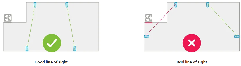
In order to provide best audio coverage in any given space,
follow these principles:
1.
Maintain a clear line of sight between audio
bars & microphone pods. The system
performs best when they have a clear, unobstructed view of each other and the
room.
2.
Avoid obstacles.
Avoid placing components behind pillars, inside alcoves and in recessed
areas.
3.
Stay clear of noise sources. Position components away from HVAC vents,
fans and other equipment that produces continuous background noise.
Audio Bar Placement
Audio bars can be mounted horizontally or vertically on the
wall using the supplied mounting bracket, or on VESA standard mounting
solutions (display mounts, floor stands, mobile carts etc).
Firstly, consider whether the space has a defined ‘front of
room’ as this is the natural focal point of a meeting or presentation where
audience attention is focused.
2 Audio Bar Solution
Ideally, for rooms with a defined front position, place 2
audio bars along this wall, evenly distributed (¼ and ¾ points on along the wall) to provide
balanced audio for both presenters and audience.
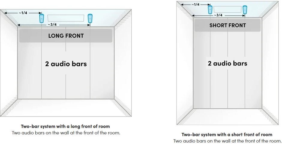
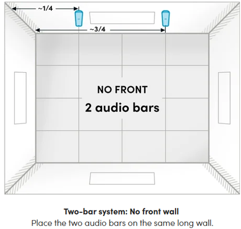
For spaces without a defined ‘front of room’, the optimal
positioning should be on the same long wall.
For more details, refer to HDX User Guide - https://www.nureva.com/user-guide/hdx/placement
4 Audio Bar Solution
Use a balanced, symmetrical layout to provide consistent
coverage across the room.
For spaces with a defined ‘front of room’, there are
multiple options for positioning.
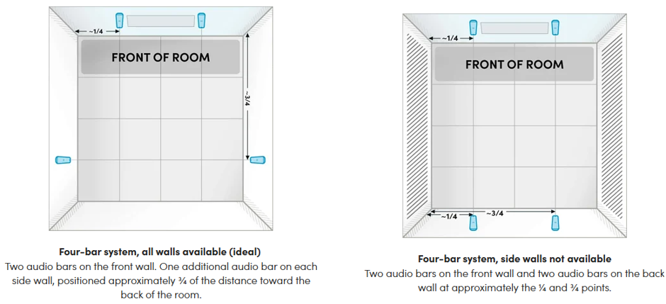
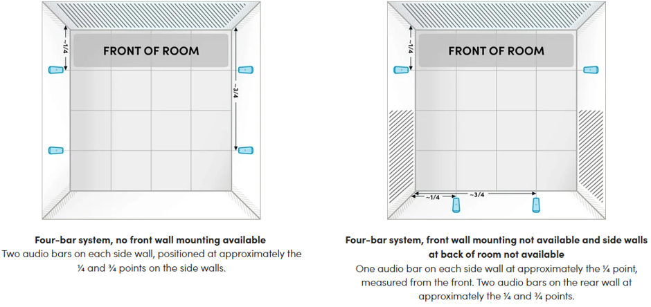
For spaces without a ‘front of room’ the bars should be
positioned evening along the long walls to provide consistent coverage.
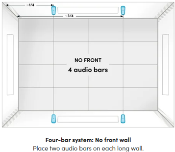
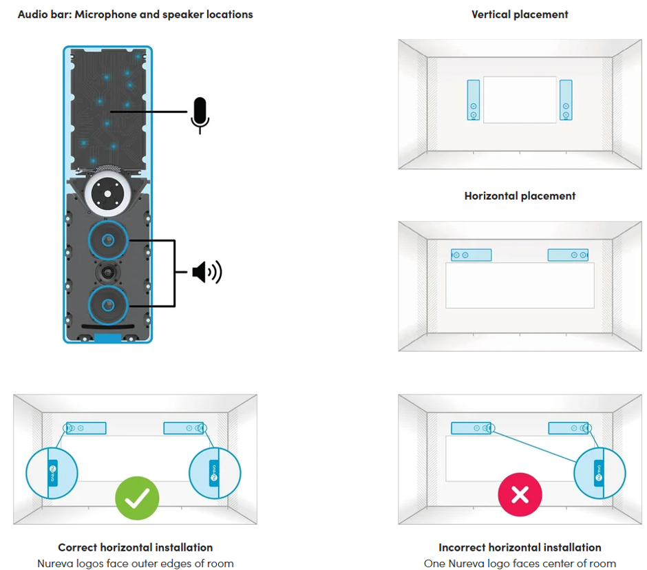
Audio Bar Orientation
HDX Audio bars can be mounted vertically or horizontally.
-
Vertical orientation (default) – microphones are
positioned in the upper half of the bar, to provide optimal localisation and
clarity
-
Horizontal orientation – the speaker drivers
need to be positioned towards the outer edges of the room for even sound
distribution. This works best when
working around windows and other obstacles.
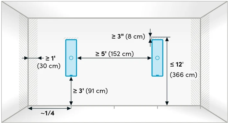
|
Guideline
|
Measurement
|
Why this
helps
|
|
Suggested
height from floor
|
91 – 366cm
|
Audio bars
being placed at or above head level will help direct sound towards listeners
and improve microphone pickup. Maintain minimum clearance of 8cm above the audio bars for wall mount
installation and service
|
|
Minimum distance
from adjacent wall or corner
|
30cm
|
Avoide
placing audio bars on walls close to corners to reduce echo. If corner placement is required, angle the
audio bars to face into the room using a VESA standard mounting solution (not
provided).
|
|
Minimum
spacing between audio bars
|
152cm
|
Adequate
space between the audio bars helps prevent them playing directly into other
components, reducing echo and supporting consistent performance
|
Microphone Pod Placement
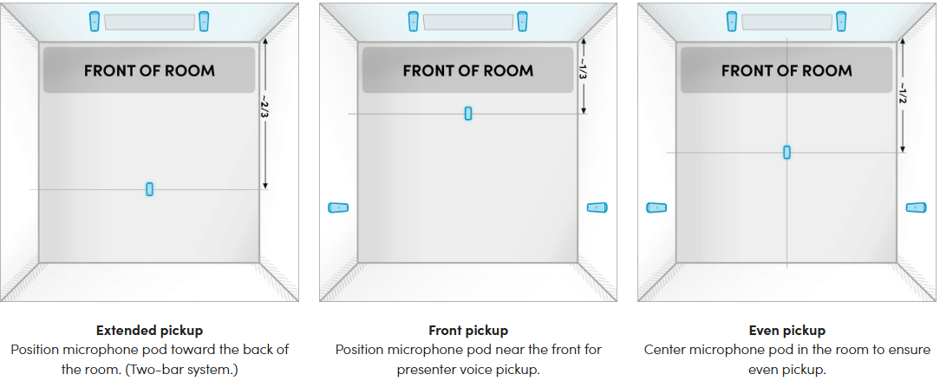
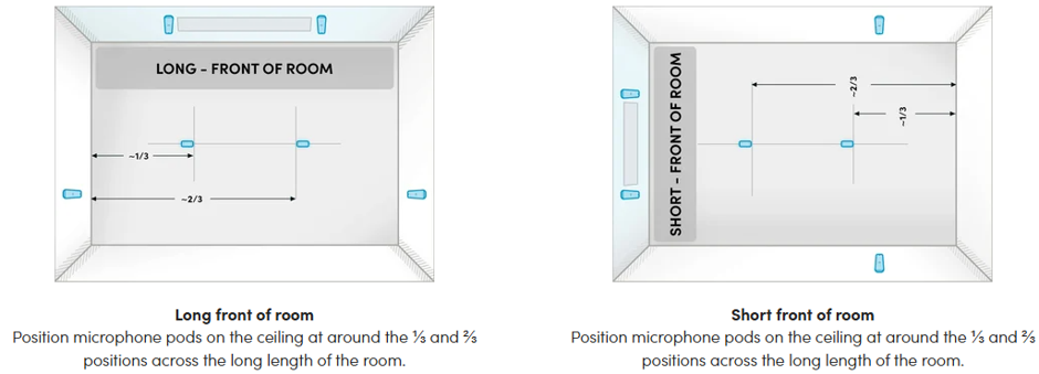
One or two microphone pods may be mounted on the ceiling, wall or VESA standard mounts, depending on room layout, furniture arrangement and location of primary talker.
The below layouts demonstrate different placement examples
but microphone placement is flexible depending on the use case.
Examples – 1 microphone pod
Examples – 2 microphones pods
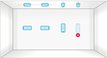
Microphone Pod installation
Installation is very flexible. The supplied bracket supports any orientation is supported except for upside down on a wall.
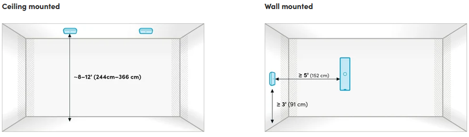
Microphone Pod Mounting Guidelines
Guideline
Measurement
Why this
helps
Typical
ceiling-mounted height
244 to366cm
The coverage
and sensitivity of the microphones are balanced, helping capture voices
clearly
Minimum wall
mount height
91cm
The placement
of microphone pods above seated height helps maintain clear pickup.
Minimum
spacing from audio bars
152cm
Adequate
spacing between microphone pods and audio bars ensures speakers and
microphones are not facing directly towards each other, reducing echo and
supporting features such as Adaptive Voice Amplification and Adaptive Voice
Lift
|
Guideline
|
Measurement
|
Why this
helps
|
|
Typical
ceiling-mounted height
|
244 to366cm
|
The coverage
and sensitivity of the microphones are balanced, helping capture voices
clearly
|
|
Minimum wall
mount height
|
91cm
|
The placement
of microphone pods above seated height helps maintain clear pickup.
|
|
Minimum
spacing from audio bars
|
152cm
|
Adequate
spacing between microphone pods and audio bars ensures speakers and
microphones are not facing directly towards each other, reducing echo and
supporting features such as Adaptive Voice Amplification and Adaptive Voice
Lift
|
System Hub Positioning
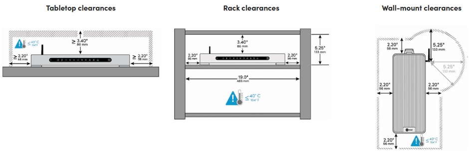
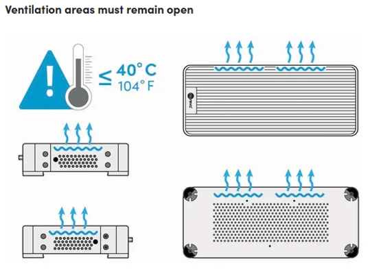
The HDX system hub can be placed on a table, shelf or rack,
or wall mounted. Regardless of
placement, ensure adequate ventilation an an unobstructed Bluetooth connection.
The HDX system hub can be placed on a table, shelf or rack,
or wall mounted. Regardless of
placement, ensure adequate ventilation an an unobstructed Bluetooth connection.
For optimal placement consider
-
Side ventilation: allow at least 56mm of
clearance
-
Top ventilation: allow at least 86mm of
clearance above
-
Heat considerations: do not install the system
hub near other devices that generate heat.
Ambient temperature must remain below 40°C
-
Bluetooth antenna: ensure it is upright for best
signal strength. Antenna extender are
not recommended.
-
Password and enrolment code are located on the
base of the system hub. Make a note of
these prior to final installation of the hub as they will be needed to enrol
system into Console.
If in doubt, Ask Ascentae
We are here to help. If you have any questions or concerns about a
solution, please contact the support team
- support@ascentae.com.